LostKiwi
Senior Member
- Joined
- Aug 25, 2006
- Messages
- 31,343
- Reaction score
- 21,602
- Location
- Midlands / Charente-Maritime
- Your Mercedes
- '93 500SL-32, '01 W210 Estate E240 (RIP), 02 R230 SL500, 04 Smart Roadster Coupe, 11 R350CDi
Recreated from Malcolms original post with pictures repaired:
http://forums.mercedesclub.org.uk/index.php?threads/the-230-can-bus-and-how-to-test.129838/
This is a guide to the CAN bus in the 230 it applies to all models right up to 2008ish. This is not an explanation of how the CAN and WAKE UP work, it is a guide to a simple way to know if your car is going to sleep, and how you can check with just 2 voltage checks. We are only dealing with CAN B as this is where all of the problems usually are.
The instrument cluster has its own Robert Bosch CAN and not included here.
An outline into the CAN.
The CAN is a high speed data bus for communication for the electrical components in the engine and body, it is also used for fault finding as any faults are logged and stored to make fault finding easier. The CAN has 2 wires only, a twisted pair these carry the CAN H for high, and the CAN L for low, should a fault occur in one of these lines, the CAN will still work on the other one, but slower.
What is a CAN System?
A CAN system is:
A digital communication link between multiple Electronic Control Modules (ECM)
A 2 wire, bi-directional communication link with data transmitted
according to priority
Message specific addressing
CAN C - Engine CAN (also known as chassis CAN)
Fast communication speeds 125 kbps or 500 kbps
CAN B - Interior CAN (also known as body CAN)
Communication speed 83 kbps
Information from CAN C can be sent to control modules on the CAN B or vice versa via the Electronic Ignition Switch (EIS). The master, the EIS is the only control module that can transfer the messages and is known as the gateway.
CAN C has priority over CAN B as CAN C controls the actual running of the car and all safety components.
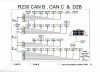
First, an outline of the connectors in the 230. They are known as X connectors (please note the all these connectors have a locking bar that un clips across the top, and the plugs cannot be removed until this locking bar is released)
The first connector in the passenger side foot well is the X30/18 Wake up with wires coloured green/white, this connects to the ignition switch.
The second connectors that also come from the ignition switch the X30/15 is the start of the CAN bus. All CAN bus wires are coloured brown and brown/red except the inter connects that join the 3 CAN connectors, these are coloured brown and brown/black.
So if there is a fault somewhere on the CAN it is quite simple to remove a brown and brown/black inter connect plug to isolate the the fault. Normally one would start with X30/15 and remove the interconnecting Brown and brown/black from connector X30/16. Now a voltage check can be done, if all the correct and normal voltages, then that interconnect can be put back and move on to the X30/16 and remove the inter connect that comes from X30/17, again check the voltages and if all are correct one can concentrate on the last one , the X30/17.

X30/18 First one next to X30/15 is the CAN C. these items seldom give any problems in the car not sleeping or any CAN faults.
EIS (N73) Ignition switch
IC (A1) Instrument cluster
SCM (N80) Steering column module
ECM (N3/10) Engine control module
DTR (N63/1) Distronic
ABC (N5/12) Suspension
ESM (N15/5) Electronic selector
ETC (N15/3) Electronic transmission control
ESP (N47-5) ESP
X30/15 The second one in the passenger side sill is the start of the CAN B.
EIS (N73) Ignition switch
IC (A1) Instrument cluster
SCM (N80) Steering column module
DCM-L (N69/1) door controllers
SAM-FL (N10/10) Front SAM L
AAC (N22) Air con
LCP (N72) Lower control panel
ESA-L (N32/1) Seat adjustment
X30/17 in the rear fuse box behind driver seat.
RVC (N52) Vario roof
SAM-Rear (N10/8) Rear SAM
PTS (N62) Parktronic
TPC (N88) Tyre pressure control
KG (N69/5) Keyless go
BNS (N82/1) Battery power supply
TELE AID (A35/8) Not in UK early cars
COMAND (A2) Comand
PSE (A37) PSE pump
X30/16 Drivers side front sill
SAM-FR (N10/11) front SAM right
OCP (N70) Over head control panel
DCM-R (N69/2) Door control L and R
SD (N55) System diagnostic connector
ESA-R (N32/2) Electric seat adjustment
Please note that Green/white wires are all wake up.
Brown and brown/red are the CAN H and L
The wires coloured Brown brown/black are the interconnects from the preceding connector or it goes to the next connector.
To test the CAN
A simple voltmeter is all that is needed, to measure any CAN voltage it is easier to lift the complete strip connector, on the rear there are 2 metal strips running the length of the connector, one is CAN H and the other CAN L.
If the car is all good and sleeping, that is with nothing running or active CAN L will have 11volts and CAN H 0.025 volts. If the car is active and one can make it active, just turn on the comand or open a door and you will see CAN L drop to 4.65 volt and CAN L go up to 0.65 volt. This voltage change when the CAN is active only last for a second and it should revert back to the dormant voltages.
When checking the voltages you must wait long enough to be sure that something is not going to try and start up, and that the car really is sleeping, that is with 11volt and 0.025 volts respectively. If these voltages are correct, then no fault.
In some cases one CAN line maybe short circuit, if this is the case then the CAN will still operate in most cases on the other CAN line, it will be much slower to operate and execute comands, this is known as the single line mode. Again this is easy to check by using the voltage checks above.
Its good if you can to keep the plugs in the same sockets on the connectors, there are no markings on the CAN plugs or wires to say what they control, and they will be positioned as in the diagram above.
This is the chart for the voltages present when active and sleeping (no activity on the CAN

Perhaps a mod can update Malcolms original thread?
http://forums.mercedesclub.org.uk/index.php?threads/the-230-can-bus-and-how-to-test.129838/
This is a guide to the CAN bus in the 230 it applies to all models right up to 2008ish. This is not an explanation of how the CAN and WAKE UP work, it is a guide to a simple way to know if your car is going to sleep, and how you can check with just 2 voltage checks. We are only dealing with CAN B as this is where all of the problems usually are.
The instrument cluster has its own Robert Bosch CAN and not included here.
An outline into the CAN.
The CAN is a high speed data bus for communication for the electrical components in the engine and body, it is also used for fault finding as any faults are logged and stored to make fault finding easier. The CAN has 2 wires only, a twisted pair these carry the CAN H for high, and the CAN L for low, should a fault occur in one of these lines, the CAN will still work on the other one, but slower.
What is a CAN System?
A CAN system is:
A digital communication link between multiple Electronic Control Modules (ECM)
A 2 wire, bi-directional communication link with data transmitted
according to priority
Message specific addressing
CAN C - Engine CAN (also known as chassis CAN)
Fast communication speeds 125 kbps or 500 kbps
CAN B - Interior CAN (also known as body CAN)
Communication speed 83 kbps
Information from CAN C can be sent to control modules on the CAN B or vice versa via the Electronic Ignition Switch (EIS). The master, the EIS is the only control module that can transfer the messages and is known as the gateway.
CAN C has priority over CAN B as CAN C controls the actual running of the car and all safety components.
First, an outline of the connectors in the 230. They are known as X connectors (please note the all these connectors have a locking bar that un clips across the top, and the plugs cannot be removed until this locking bar is released)
The first connector in the passenger side foot well is the X30/18 Wake up with wires coloured green/white, this connects to the ignition switch.
The second connectors that also come from the ignition switch the X30/15 is the start of the CAN bus. All CAN bus wires are coloured brown and brown/red except the inter connects that join the 3 CAN connectors, these are coloured brown and brown/black.
So if there is a fault somewhere on the CAN it is quite simple to remove a brown and brown/black inter connect plug to isolate the the fault. Normally one would start with X30/15 and remove the interconnecting Brown and brown/black from connector X30/16. Now a voltage check can be done, if all the correct and normal voltages, then that interconnect can be put back and move on to the X30/16 and remove the inter connect that comes from X30/17, again check the voltages and if all are correct one can concentrate on the last one , the X30/17.
X30/18 First one next to X30/15 is the CAN C. these items seldom give any problems in the car not sleeping or any CAN faults.
EIS (N73) Ignition switch
IC (A1) Instrument cluster
SCM (N80) Steering column module
ECM (N3/10) Engine control module
DTR (N63/1) Distronic
ABC (N5/12) Suspension
ESM (N15/5) Electronic selector
ETC (N15/3) Electronic transmission control
ESP (N47-5) ESP
X30/15 The second one in the passenger side sill is the start of the CAN B.
EIS (N73) Ignition switch
IC (A1) Instrument cluster
SCM (N80) Steering column module
DCM-L (N69/1) door controllers
SAM-FL (N10/10) Front SAM L
AAC (N22) Air con
LCP (N72) Lower control panel
ESA-L (N32/1) Seat adjustment
X30/17 in the rear fuse box behind driver seat.
RVC (N52) Vario roof
SAM-Rear (N10/8) Rear SAM
PTS (N62) Parktronic
TPC (N88) Tyre pressure control
KG (N69/5) Keyless go
BNS (N82/1) Battery power supply
TELE AID (A35/8) Not in UK early cars
COMAND (A2) Comand
PSE (A37) PSE pump
X30/16 Drivers side front sill
SAM-FR (N10/11) front SAM right
OCP (N70) Over head control panel
DCM-R (N69/2) Door control L and R
SD (N55) System diagnostic connector
ESA-R (N32/2) Electric seat adjustment
Please note that Green/white wires are all wake up.
Brown and brown/red are the CAN H and L
The wires coloured Brown brown/black are the interconnects from the preceding connector or it goes to the next connector.
To test the CAN
A simple voltmeter is all that is needed, to measure any CAN voltage it is easier to lift the complete strip connector, on the rear there are 2 metal strips running the length of the connector, one is CAN H and the other CAN L.
If the car is all good and sleeping, that is with nothing running or active CAN L will have 11volts and CAN H 0.025 volts. If the car is active and one can make it active, just turn on the comand or open a door and you will see CAN L drop to 4.65 volt and CAN L go up to 0.65 volt. This voltage change when the CAN is active only last for a second and it should revert back to the dormant voltages.
When checking the voltages you must wait long enough to be sure that something is not going to try and start up, and that the car really is sleeping, that is with 11volt and 0.025 volts respectively. If these voltages are correct, then no fault.
In some cases one CAN line maybe short circuit, if this is the case then the CAN will still operate in most cases on the other CAN line, it will be much slower to operate and execute comands, this is known as the single line mode. Again this is easy to check by using the voltage checks above.
Its good if you can to keep the plugs in the same sockets on the connectors, there are no markings on the CAN plugs or wires to say what they control, and they will be positioned as in the diagram above.
This is the chart for the voltages present when active and sleeping (no activity on the CAN
Perhaps a mod can update Malcolms original thread?
Attachments
Last edited: