gusvlachos
Member
- Joined
- May 8, 2009
- Messages
- 14
- Reaction score
- 0
- Location
- East coast, Athens -Greece
- Your Mercedes
- MB w203,Getz 1.6,Elan+2,2Racing minis
TPS: FAILING SYMPTOMS, TESTING, REPAIRING(the most)
-------------------------------------------------
W 203 early model 06/2000(M111) TPS, with kickdown switch, 20k miles on. Probably applies to more recent version as well, as other engines(M112, ..), which use "hall effect" TPS sensors.
----------------------------------------------
Applies to those members, who can't afford, or they don't want to pay high bills in MB dealers, and have some DIY skills. All others
who can afford high costs, they haven't to worry, bother themselves, or spend time, ..., just pay!
---------------------------------------------
SYMPTOMS:
---------
1)Engine starts ok, idle ok.
2)Any time you press accel./pedal(..driving, or shifting gears, or idling ), no instant power, but comes after 3-5 secs delay, and ends in a limp
mode or reduced power.(no kompressor boost- where available).
3)If you press slowly pedal, things are going little better, but ends with same un drivable way.
4)Once in a week or so, car may work perfect!!
This is the situation, you have to reach, before proceed a TPS test. All others, who notice a rare power delay/loss, and after restarting the
problem has gone, they have the time, soon or later will notice same symptoms, as TPS voltage setup fails.
---------------------------------------------
ERROR CODES:
------------
Some cases, put the correct TPS codes P0120, P0121.., Other instead (many cases in the forums, as well as mine) , give MAF error codes, P0100, P0101, misfiring codes P0300, ..thus driving to MAF replace (I try this also).There is an explanation for it.(optional issue)
No matter if you erase the codes from the memo, after some driving circles, codes reoccur as stored or pending errors, in moderate revs.
So, in this point always proceed an unplugged MAF test. If the problem remain, re-plug your MAF, it is OK, and proceed a TPS test, is the most
suspicious.
---------------------------------------------
TOOLS:
------
1) A reliable voltmeter/multimeter
2) A household battery supply of 5v, or more if using a variable resistor. The target is: to obtain a testing voltage from the battery equals to
the measurement we'll get later from the ECU/ECM (N3/10 ME-SFI) voltage supply, to TPS connector.(You can achieve this using some old 1.5v, 4.5v&
doing comps).The correct is, to use a variable resistor-is cheap. This is important to obtain accurate measures, from TPS Sensor later.
3) Two pieces of ?:1, 5mm wire, 1/2 meter long.
4) Two needles(pins), to put firmly in multimeter's leads with tape, to reach connector's narrow pins.
PROCEDURE:
----------
1) Remove keys
2) Remove TPS assembly, as follow:
a)remove tap in the pedal base to see the holding nut. Undo nut, and raise a bit the pedal to give room.
b)Unplug beneath pedal the kickdown switch(k/S) connector. Us your fingers, or a bended long iron nail, and a mirror to see what you doing (if exists-till 4/2002).
c)Unplug the TPS 6pin connector in the right side, now you are ready to get the sensor off.
d)By moving it left/right and pulling towards you, and then turning upwards you take it out in the bench. It is easy.[if you find difficulty,
release plastic panel (3torxs) to make some room, taking care to bonnet release knob & diagnostic socket (LHD)].
WARNING:
--------
Before work on any electronic device's connector pins, always degauss yourself, by touching a good ground (house water tubes..), to
prevent static sparks, are lethal it.
N3/10 ME-SFI(ECU), OUTPUT VOLTAGE TEST TO TPS:
---------------------------------------------
For this testing ,turn switch on(cluster lamps on/II keys position!), after finish remove keys again.
In the unplugged TPS connector in the MB floor, measure voltages at pins 1(+) & 6(ground), then at 1(+) & 3(ground)..These has to be between
(4.75v-5.25v) limit. If so, this says that grounds is ok in ECU, and Signals 1&2(S1)&(S2) of sensor is supplied with correct voltage. Now NOTE voltage (e.g. 5.010v).This volt value have to be achieved in the test battery for accurate setup. We are ready now for TPS test. AVOID accidental short circuits during measures. Do CAREFULLY, and everything will work.
TPS INFORMATION:
----------------
As I guess out dealing with this problem, generally the sensor uses the "hall effect" principle in order to avoid rapid use wear, (in comparison with old type variable resistors sensors), by no friction between moving parts. This is true for 1/3, 2/3, 3/3 sensor's positions, but not in the idle position. And I guess this is the weak point of TPS. After so many times of pressing and releasing the pedal, as time goes by (mostly from sudden releases), the pedal & sensor has to return back to its stop rather vigorously, (with help from a rather hard returning spring), driving this to change its original stop position, resulting TPS's idle voltage setup, out of calibration. Then all above symptoms occurs. With this in mind, I gave the follow easy solution, (no TPS dismantling required).
TPS VOLTAGE TESTS:
---------------------
Hold STEADY the TPS in the bench, (use carpenter's catcher tool or so..) .
Prepare the test battery with the CORRECT " previous noted" voltage of ECU output measure, (e.g. 5, 010v), and bring it near TPS. This voltage ECU recognised as a volt referring value for setups.
Take one piece of wire, and bare one side for connection to batt.(+) , cut the other side clearly, and insert a needle to make a room, prior to insert it down with care, to pin(1) male of TPS connector. This is the (+) TPS feed for test. You don't have to move it again, before test is completed.
Take the other wire, bare one end for connection to batt (-), the other end bare it about 3mm and twist it firmly then bend it back, and make a needle room, prior to insert it in pin(3) male, of connector. This is (-) feeding for S2 (low signal), & S1 (high signal) after.
To measure S2 signal, just put voltmeters leads to touch, 3mm bare twisted wire in pin(3) (black lead) , and the (red lead) in pin(4), the value you get is idle S2 signal, and have to be over 0, 100v (in faulty TPS goes around 0, 050v-0, 080v). Remember always to make S2 signal test first, because S2 gets lower faulty values, than S1 do. AVOID accidental s/c!
To measure S1 signal just remove the 3mm bare wire from pin(3) to pin(6), and measure value between pin(6)(black lead) and pin(5)(red lead),
the value is the idle S1 signal, and have to be over 0, 200v, (in faulty TPS goes around 0, 150v-0, 170v).
THESE LOW VOLT IDLE MEASURES ARE THE CAUSE, THAT PRODUCE POWER DELAY/LOSS BY GIVING WRONG SETUP INFORMATION TO ECU.
You can check also S1 & S2 volt values, at 1/3, 2/3, 3/3 & K/S positions (highest volt value). Maximum voltage have to be <4, 990v, but I'm guess
you'll find all ok. Also check, that S1 values are approx. double than S2 are, in each pedal position measure.(ignore pin2).
Follow this pins sequence measures (accelerator error2.pdf ) , though some diagrams give wrong volt pins testing.
TPS REPAIRING:
--------------
WHAT WE TRY to achieve by following trick, are: a) To get a S2 value at idle position, around ( 0, 140v min - 0, 180v max ), thus the S1 values will give somehow (0, 320v - 0, 380v ) max .[You'll notice that deviation (dV) in S1, S2 signals, is over 8% than specification give, (actually is up to 13% approx), but ignore it, nothing you can do. No big problem . Mine reach over 32% , and no error code putted. I think in volt setup for ECU, is far important (hi-lo) S1, S2 idle volt limits, than the deviation}.The equation is dV% = (S1/S2x2-1)x100. Any way don't over pass maximums, because idle will rev to 1500rpm.
b) To make a good feel, time last pedal stop.
THE TRICK:
----------
Is simple, raise the TPS cover by unclicking side clicks & remove it.
Insert (not permanently) two plastic pieces of PVC (3, 0-3, 2mm panel's thick) till to TPS surface (for free TPS cover reclose), in the corners at inner sides of TPS, where the pedal rest and leaves an approx. 3mm-4mm gaps, (L-R gaps are not symmetric), (Attached diagram, red arrows).
The starting dimensions of plastic pieces, are approx.: LEFT SIDE 5, 2X20, 0 mm, RIGHT SIDE 4, 2X9, 0 mm(no much room for longer insert).
Proceed now in TPS volt testing as described above, and do any changes to PVC width (using a grinder), prior to obtain desirable S2 value(0, 140v-0, 180vmax).Then check S1 value. If all are OK, go to next final step.
FINAL STEP-WARNINGS:
--------------------
A)The PVC pieces must have nice square cuts, be CLEAN, and seat well in CLEAN TPS corners.
B)The moving pedal's stop, has to touch both PVC pieces simultaneously, when returns.
C)At final stage, these pieces has to be SECURE for falling down, to AVOID troubles.
After gluing (I use UHU universal, is more elastic) , put a TAILORED STEEL CLIP for chassis holds, to secure for sure the pieces with TPS walls, and use a hair drier for a while to dry glue, prior to put a second overlay .During heating, force pedal backward to make a good stop seat, between PVC pieces & pedal's stop. AVOID glue, from stop points. AVOID/PROTECT sensor's overheating.
D)Use quality materials and your skill, to make a quality job.
E)The pedal must move freely to its travel. After that, leave it for some hours to dry, and..
F)Read well all above, and if you think your skills are not enough, DON'T do.
As a final touch, before close TPS cover, lubricate with silicone the two plastic axles of pedal motion.
Now recheck pedal's free travel, and feel how good is the stop feeling, instead of previous sluggish one, (it'll last long more, than its original fitting).
Put TPS back, in reverse action, make a TPS RESETTING, ( NOT by disconnecting battery ), and go for a ride to teach your ECU. The car will kill, costless, with 2-3 hours labour.
GOOD LUCK to all
GUS
-------------------------------------------------
W 203 early model 06/2000(M111) TPS, with kickdown switch, 20k miles on. Probably applies to more recent version as well, as other engines(M112, ..), which use "hall effect" TPS sensors.
----------------------------------------------
Applies to those members, who can't afford, or they don't want to pay high bills in MB dealers, and have some DIY skills. All others
who can afford high costs, they haven't to worry, bother themselves, or spend time, ..., just pay!
---------------------------------------------
SYMPTOMS:
---------
1)Engine starts ok, idle ok.
2)Any time you press accel./pedal(..driving, or shifting gears, or idling ), no instant power, but comes after 3-5 secs delay, and ends in a limp
mode or reduced power.(no kompressor boost- where available).
3)If you press slowly pedal, things are going little better, but ends with same un drivable way.
4)Once in a week or so, car may work perfect!!
This is the situation, you have to reach, before proceed a TPS test. All others, who notice a rare power delay/loss, and after restarting the
problem has gone, they have the time, soon or later will notice same symptoms, as TPS voltage setup fails.
---------------------------------------------
ERROR CODES:
------------
Some cases, put the correct TPS codes P0120, P0121.., Other instead (many cases in the forums, as well as mine) , give MAF error codes, P0100, P0101, misfiring codes P0300, ..thus driving to MAF replace (I try this also).There is an explanation for it.(optional issue)
No matter if you erase the codes from the memo, after some driving circles, codes reoccur as stored or pending errors, in moderate revs.
So, in this point always proceed an unplugged MAF test. If the problem remain, re-plug your MAF, it is OK, and proceed a TPS test, is the most
suspicious.
---------------------------------------------
TOOLS:
------
1) A reliable voltmeter/multimeter
2) A household battery supply of 5v, or more if using a variable resistor. The target is: to obtain a testing voltage from the battery equals to
the measurement we'll get later from the ECU/ECM (N3/10 ME-SFI) voltage supply, to TPS connector.(You can achieve this using some old 1.5v, 4.5v&
doing comps).The correct is, to use a variable resistor-is cheap. This is important to obtain accurate measures, from TPS Sensor later.
3) Two pieces of ?:1, 5mm wire, 1/2 meter long.
4) Two needles(pins), to put firmly in multimeter's leads with tape, to reach connector's narrow pins.
PROCEDURE:
----------
1) Remove keys
2) Remove TPS assembly, as follow:
a)remove tap in the pedal base to see the holding nut. Undo nut, and raise a bit the pedal to give room.
b)Unplug beneath pedal the kickdown switch(k/S) connector. Us your fingers, or a bended long iron nail, and a mirror to see what you doing (if exists-till 4/2002).
c)Unplug the TPS 6pin connector in the right side, now you are ready to get the sensor off.
d)By moving it left/right and pulling towards you, and then turning upwards you take it out in the bench. It is easy.[if you find difficulty,
release plastic panel (3torxs) to make some room, taking care to bonnet release knob & diagnostic socket (LHD)].
WARNING:
--------
Before work on any electronic device's connector pins, always degauss yourself, by touching a good ground (house water tubes..), to
prevent static sparks, are lethal it.
N3/10 ME-SFI(ECU), OUTPUT VOLTAGE TEST TO TPS:
---------------------------------------------
For this testing ,turn switch on(cluster lamps on/II keys position!), after finish remove keys again.
In the unplugged TPS connector in the MB floor, measure voltages at pins 1(+) & 6(ground), then at 1(+) & 3(ground)..These has to be between
(4.75v-5.25v) limit. If so, this says that grounds is ok in ECU, and Signals 1&2(S1)&(S2) of sensor is supplied with correct voltage. Now NOTE voltage (e.g. 5.010v).This volt value have to be achieved in the test battery for accurate setup. We are ready now for TPS test. AVOID accidental short circuits during measures. Do CAREFULLY, and everything will work.
TPS INFORMATION:
----------------
As I guess out dealing with this problem, generally the sensor uses the "hall effect" principle in order to avoid rapid use wear, (in comparison with old type variable resistors sensors), by no friction between moving parts. This is true for 1/3, 2/3, 3/3 sensor's positions, but not in the idle position. And I guess this is the weak point of TPS. After so many times of pressing and releasing the pedal, as time goes by (mostly from sudden releases), the pedal & sensor has to return back to its stop rather vigorously, (with help from a rather hard returning spring), driving this to change its original stop position, resulting TPS's idle voltage setup, out of calibration. Then all above symptoms occurs. With this in mind, I gave the follow easy solution, (no TPS dismantling required).
TPS VOLTAGE TESTS:
---------------------
Hold STEADY the TPS in the bench, (use carpenter's catcher tool or so..) .
Prepare the test battery with the CORRECT " previous noted" voltage of ECU output measure, (e.g. 5, 010v), and bring it near TPS. This voltage ECU recognised as a volt referring value for setups.
Take one piece of wire, and bare one side for connection to batt.(+) , cut the other side clearly, and insert a needle to make a room, prior to insert it down with care, to pin(1) male of TPS connector. This is the (+) TPS feed for test. You don't have to move it again, before test is completed.
Take the other wire, bare one end for connection to batt (-), the other end bare it about 3mm and twist it firmly then bend it back, and make a needle room, prior to insert it in pin(3) male, of connector. This is (-) feeding for S2 (low signal), & S1 (high signal) after.
To measure S2 signal, just put voltmeters leads to touch, 3mm bare twisted wire in pin(3) (black lead) , and the (red lead) in pin(4), the value you get is idle S2 signal, and have to be over 0, 100v (in faulty TPS goes around 0, 050v-0, 080v). Remember always to make S2 signal test first, because S2 gets lower faulty values, than S1 do. AVOID accidental s/c!
To measure S1 signal just remove the 3mm bare wire from pin(3) to pin(6), and measure value between pin(6)(black lead) and pin(5)(red lead),
the value is the idle S1 signal, and have to be over 0, 200v, (in faulty TPS goes around 0, 150v-0, 170v).
THESE LOW VOLT IDLE MEASURES ARE THE CAUSE, THAT PRODUCE POWER DELAY/LOSS BY GIVING WRONG SETUP INFORMATION TO ECU.
You can check also S1 & S2 volt values, at 1/3, 2/3, 3/3 & K/S positions (highest volt value). Maximum voltage have to be <4, 990v, but I'm guess
you'll find all ok. Also check, that S1 values are approx. double than S2 are, in each pedal position measure.(ignore pin2).
Follow this pins sequence measures (accelerator error2.pdf ) , though some diagrams give wrong volt pins testing.
TPS REPAIRING:
--------------
WHAT WE TRY to achieve by following trick, are: a) To get a S2 value at idle position, around ( 0, 140v min - 0, 180v max ), thus the S1 values will give somehow (0, 320v - 0, 380v ) max .[You'll notice that deviation (dV) in S1, S2 signals, is over 8% than specification give, (actually is up to 13% approx), but ignore it, nothing you can do. No big problem . Mine reach over 32% , and no error code putted. I think in volt setup for ECU, is far important (hi-lo) S1, S2 idle volt limits, than the deviation}.The equation is dV% = (S1/S2x2-1)x100. Any way don't over pass maximums, because idle will rev to 1500rpm.
b) To make a good feel, time last pedal stop.
THE TRICK:
----------
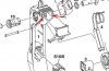
Is simple, raise the TPS cover by unclicking side clicks & remove it.
Insert (not permanently) two plastic pieces of PVC (3, 0-3, 2mm panel's thick) till to TPS surface (for free TPS cover reclose), in the corners at inner sides of TPS, where the pedal rest and leaves an approx. 3mm-4mm gaps, (L-R gaps are not symmetric), (Attached diagram, red arrows).
The starting dimensions of plastic pieces, are approx.: LEFT SIDE 5, 2X20, 0 mm, RIGHT SIDE 4, 2X9, 0 mm(no much room for longer insert).
Proceed now in TPS volt testing as described above, and do any changes to PVC width (using a grinder), prior to obtain desirable S2 value(0, 140v-0, 180vmax).Then check S1 value. If all are OK, go to next final step.
FINAL STEP-WARNINGS:
--------------------
A)The PVC pieces must have nice square cuts, be CLEAN, and seat well in CLEAN TPS corners.
B)The moving pedal's stop, has to touch both PVC pieces simultaneously, when returns.
C)At final stage, these pieces has to be SECURE for falling down, to AVOID troubles.
After gluing (I use UHU universal, is more elastic) , put a TAILORED STEEL CLIP for chassis holds, to secure for sure the pieces with TPS walls, and use a hair drier for a while to dry glue, prior to put a second overlay .During heating, force pedal backward to make a good stop seat, between PVC pieces & pedal's stop. AVOID glue, from stop points. AVOID/PROTECT sensor's overheating.
D)Use quality materials and your skill, to make a quality job.
E)The pedal must move freely to its travel. After that, leave it for some hours to dry, and..
F)Read well all above, and if you think your skills are not enough, DON'T do.
As a final touch, before close TPS cover, lubricate with silicone the two plastic axles of pedal motion.
Now recheck pedal's free travel, and feel how good is the stop feeling, instead of previous sluggish one, (it'll last long more, than its original fitting).
Put TPS back, in reverse action, make a TPS RESETTING, ( NOT by disconnecting battery ), and go for a ride to teach your ECU. The car will kill, costless, with 2-3 hours labour.
GOOD LUCK to all
GUS
Attachments
Last edited by a moderator:
