V6 CDI Inlet Port Shut Off Motor Replacement

M80

Senior Member
Joined
Jan 21, 2006
Messages
5,949
Reaction score
2,756
Location
Derbyshire
Your Mercedes
2014 639 Viano- 651, 5sp Auto. 2009 S211- 646, 5sp Auto.
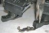
In preparation I think it’s worth dropping the belly pans. The 1st time you drop a bolt or socket the pans have to be dropped anyway, this way now you just pull out the belly pan to recover the dropsy. Then put the belly pan back to catch the next.

When feasible I prefer to remove the item and screw bolts back where they came from to reduce the confusion of “where’s this one from”.

Setting up with torches, grab claw, extendable magnetic led and masking tape were very useful.
A roll of ‘heavy duty’ kitchen type roll from the £ shop worked a treat, as did a few pairs of the blue nitrile gloves.

To clean I spray white spirit onto the towel and wipe.
_______________________________________
The fault was the car going into limp home mode.
Various fault codes were present but many due to the under bonnet fuse number 54 (15 amp) having been blown by the inlet port shut off motor.
A known problem is the air intake duct is sealed to the turbo Intake spigot by a rubber seal. This seal allows oil to pass that finds it’s way onto the shut off motor below, causing it’s eventual failure.
_________________________________________

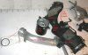
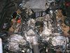
Remove engine cover.

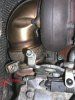
Remove heat shield above turbo,
3 bolts, image (b).

Remove o/s heat shield support bracket (engine hoist point),
2 bolts

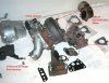
Remove air filter retaining bolts,
2x2, 4 bolts in all.

Loosen jubilee’s on air filter to air intake duct, ease air filters sideways away from engine,
2 jubilee’s.

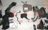
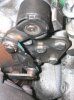
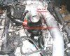
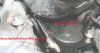
Unplug 2 MAF’s at air intake duct,
image (a).

Remove PCV inline heater from air intake duct and unplug, this will need to be moved away from the work area,
image (a).
If you wish to replace the rubber seal consider that this is supplied c/w a heater, £22 +vat.
Mine was passing oil and was an unreliable seal into the duct.
A new one will be more difficult to push into the duct on re-assembly.

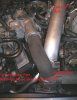
At air duct to turbo spigot loosen the jubilee, and ease air duct backward and off,
image (b)
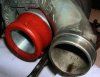
We are now up to the 3rd revision in design of the air duct (approx £250 +vat). The new style rubber seal between air duct and turbo intake spigot, ‘the cause of the issue’ is now shorter but also fatter. On re-assembly pushing the seal onto the spigot is very difficult, maybe the later design makes for this to be easier ? Don’t loosen the jubilee to much at re-assembly as it offers support to the plastic surround and can prevent it splitting.
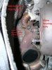
I ran a bead of silicon sealant around the inside of the air duct where the seal sits, looking at the old seal there was a gap between the seal and the turbo intake spigot (see image (o)). This would allow the oil to pool and eventually run, I hope to prevent any repeat of this.

image (n) & image (o).
*
*
 

Attachments

  • (a) Bench layout, front.jpg
    (a) Bench layout, front.jpg
    306.2 KB · Views: 7,532
  • (b) Bench layout, mid.jpg
    (b) Bench layout, mid.jpg
    424 KB · Views: 7,143
  • (c) Bench layout, rear.jpg
    (c) Bench layout, rear.jpg
    385.9 KB · Views: 6,739
  • (n) compare new-old seals.JPG
    (n) compare new-old seals.JPG
    372.1 KB · Views: 4,853
  • (o) original seal on spigot...jpg
    (o) original seal on spigot...jpg
    471.7 KB · Views: 4,873
OP
M80

M80

Senior Member
Joined
Jan 21, 2006
Messages
5,949
Reaction score
2,756
Location
Derbyshire
Your Mercedes
2014 639 Viano- 651, 5sp Auto. 2009 S211- 646, 5sp Auto.
  • Thread Starter
  • Thread starter
  • #2
V6 CDI Inlet Port Shut Off Motor Replacement (Part 2)

At the turbo actuator carefully prise off the spring clip at the top linkage, separate linkage from actuator. Tape the linkage to prevent the bearing coming out and to stop the linkage being a nuisance,
image (d).

Remove the bolts from the back of the actuator bracket that bolt it to the turbo, remove actuator,
3 bolts.

At the exhaust output elbow at the rear of the turbo loosen the lower clamp and ease off the joint. This can be left on the elbow when removed,
1 bolt, image (e).

At the back of the turbo loosen and remove the top 2 bolts of the exhaust elbow. Only loosen the lower bolt as the lower of the flange is slotted, the elbow will than lift away.
Good luck with the lower bolt, it’s a bitch.
3 bolts, image (f).

On re-assembly the new gasket has 2 locating plastic pegs. I removed the n/s peg and prised the o/s peg for easier removal when the elbow had been fitted. The 1 peg and the lower bolt are good enough for locating,
image (c).

Remove the EGR exhaust flexi feed pipe. Some caution there are 2 gaskets that might want to fall.
Protect the manifold hole with masking tape.
4 bolts total, 2 long ones into the head,
image (f).

It’s possible at re-assembly to pass the bolts through to the gaskets to hold the gaskets in place while the flexi pipe is re-installed,
image (c).

Remove bolts from exhaust into turbo manifold, be aware of the 2 gaskets that may fall,
2x3 bolts, 6 bolts total, image (g) & image (c).

On re-assembly prepare by 1st checking orientation of the 2 gaskets to understand how they go at 1st attempt,

image (c).

Remove bolts clamping lower bracket to lower exhaust side of turbo exhaust intake manifold,
2 bolts, image (f).

At re-assembly replace these 2 bolts and tighten prior to replacement of lower bolt on o/s exhaust into turbo manifold or the lower bolt will obstruct. The other 5 exhaust bolts want to be close to tight prior to tightening the lower bracket to turbo 2 bolts.

It may be easier to remove the low vertical bolts that hold the lower bracket to the block, the lower bracket will lift out with the turbo assembly as will the turbo actuator. For re-assembly I found removing the lower clamp and actuator reduced weight and made for easier re-siting of the turbo assembly,

image (g).

*
*
 

Attachments

  • (d) Rear of turbo actuator, intact..jpg
    (d) Rear of turbo actuator, intact..jpg
    480.1 KB · Views: 6,384
  • (e) Rear of turbo, exhaust elbow, intact..jpg
    (e) Rear of turbo, exhaust elbow, intact..jpg
    493.2 KB · Views: 5,904
  • (f)) Exhaust out elbow removed, see EGR in- flexi..jpg
    (f)) Exhaust out elbow removed, see EGR in- flexi..jpg
    426.3 KB · Views: 5,579
  • (g) Closer view of rear, all rmoved..jpg
    (g) Closer view of rear, all rmoved..jpg
    518.9 KB · Views: 5,904
OP
M80

M80

Senior Member
Joined
Jan 21, 2006
Messages
5,949
Reaction score
2,756
Location
Derbyshire
Your Mercedes
2014 639 Viano- 651, 5sp Auto. 2009 S211- 646, 5sp Auto.
  • Thread Starter
  • Thread starter
  • #3
V6 CDI Inlet Port Shut Off Motor Replacement (Part 3)

Now to top and front of engine.

Unclip coolant pipe from front of the intercooler to turbo pipe.
Unscrew horse shoe retaining screw at top of intercooler and withdraw horse shoe, some leverage may be needed.
At the middle area of the intercooler pipe remove the tall post bolt,
1 screw, 1 bolt, image (h).

At the bracket to the front of the turbo remove the bolt into the turbo, the bolt down into the shut off motor, and the 2 bolts into the head. Remove bracket,
4 bolts total, image (j).

Remove bolts that clamp the turbo onto the turbo tower,
2 bolts, image (b).

The turbo should allow enough play to remove the intercooler pipe.

At re-assembly it may be preferable to replace the black ‘o’ ring onto the intercooler and the green ‘o’ ring onto the turbo output spigot.

At the fuel rail link pipe remove the 2 clamp bolts and ease the clamps and rubbers off the link fuel pipe,
Loosen the fuel link pipe at each fuel rail, some leverage will make it possible to remove the fuel link pipe, too much leverage could cause the pipe to kink.
2 bolts. 2 nuts, image (j).


Loosen the rubber fuel pipe jubilee’s at the fuel filter and slide rubber fuel pipes backward,
2 jubilee’s.

1 more bolt to remove and the fuel filter can be lifted out.
1 bolt.

The turbo now needs to be angle rearward so that access to the lower tower bolts can be gained, remove the lower bolts, remove the tower while manipulating the turbo.
4 bolts, image (b).

There is likely to be some muck around so carefully remove any obvious muck and protecting the oil ways with some tissue is a good idea.

It should be possible to lift out the turbo c/w the exhaust turbo manifold,
image (b).

On re-assembly the gasket clips to the underside of the turbo and stays in place. The lower gasket sits on dowels in the engine block,
image (b) & image (g).

Protect the exhaust into turbo manifold holes, I used kitchen roll,
image (g).

Unbolt and remove lower bracket if not already done earlier and if desired,
2 bolts, image (g).

The under turbo wiring loom duct is held by a plastic clip sitting onto a bracket near dip stick, into the engine hoist point bracket, and 1 bolt into the head.
The duct can be moved a good way to create work space,
1 bolt, image (k).

With snipe nose pliers apply gentle pressure to plastic insert above motor arm pivot points.
It’s easier on re-assembly to insert the retainers into the motor arms rather than at the outer port linkages.
Ease down by pulling from below.
Be aware that the plastic inserts are in 2 halves and may separate when removed.
2 pivot retainers, image (l) & image (c).

Unplug and remove Inlet Port Shut off motor,
2 bolts, image (m) & image (b).

Being cautious not to contaminate the turbo tower oil ways there is now likely to be much muck from the escaped oil to be cleaned.
I used kitchen roll to protect the oil ways.
Check the ports open / close freely by manipulating the below head linkages.
________________________________

I would suggest that there is a good days work to replace the shut off motor and rebuild. This depends on how easy or (more likely) difficult the bolts come out.
Many are very difficult to get to, and big hands would be a disadvantage.
I didn’t rush, carried out the task in an organised way and took a lot longer.
Total cost for parts at 10% discount for asking, £255.36 Incl Vat.
*
*
 

Attachments

  • (h) Engine front, intact.jpg
    (h) Engine front, intact.jpg
    477.8 KB · Views: 5,691
  • (j) Area, part dismantleda.jpg
    (j) Area, part dismantleda.jpg
    523 KB · Views: 6,350
  • (k) Over view, all out..jpg
    (k) Over view, all out..jpg
    554.6 KB · Views: 6,350
  • (l) Release of plastic retainer on motor linkage pivot..jpg
    (l) Release of plastic retainer on motor linkage pivot..jpg
    461.8 KB · Views: 5,701
  • (m) Shut off motor, 2 securing bolts..jpg
    (m) Shut off motor, 2 securing bolts..jpg
    280.5 KB · Views: 5,710

You lost your key ? Or maybe you need a spare! Your vehicle imobilliser does not respond anymore? WE CAN FIX THEM ALL !! Mobile ! Save Time and Increase Profits With us !
Top Bottom