aycee
Senior Member
- Joined
- May 28, 2008
- Messages
- 437
- Reaction score
- 3
- Location
- Headley, Hampshire
- Your Mercedes
- Black CLS350 W218, Blue SLK320 R170, Silver A Class W169
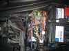
Below are the the processes I went through to install the modules. I followed the instructions on the supplied sheets. There are two modules and a relay to install. The instructions are very good but they are for left hand drive cars so have to view the pictures as a mirror image. The fuse box and ECU box are the other way round.
Although I used crimp connectors once I tested the roof and it all worked I went back and soldered the cables. Didn’t have too much confidence in my crimping skills.
You will need:
• Wire cutters
• Wire strippers
• Crimping tool
• Pliers
• Small flat screwdriver
• Small sockets (10mm & 8mm)
• 1 Large Scotch lock (Yellow)
• 3 Medium Scotch locks (Blue)
• 3 Small Scotch locks (Red)
• inline crimp connectors or solder and shrink fit tubing
• Double sided pads or Velcro
• Some cable ties
The first module allows the roof to be opened/closed whilst the car is moving. This must be fitted and tested before fitting the other module and relay.
The second module controls the roof.
The relay provides power to the roof module
Stage 1 - 50 Km/h Module
1 Make sure you have your radio code.
2 Disconnect the negative side of the battery.
3 Open up the ECU box which is next to the battery (slide back the clips).
4 Cut and remove the black cable tie to free up the cables.
5 Locate the ECU-SKF module.
6 Locate the pink/yellow/green wire (Pin 3) and using the large scotch lock connect the red wire from the module.
7 Locate the brown wire (Pin 42) and connect it to the black wire on the module with a scotch lock.
8 Locate the green/white wire (Pin 74) and cut it.
9 Connect the ECU side to the white wire with a crimped connector.
10 Connect the wiring loom side to the green wire.
11 Locate the blue/green wire (Pin 56) and cut it.
12 Connect the ECU side to the yellow wire with a crimped connector.
13 Connect the wiring loom side to the blue wire.
14 There is enough room inside the ECU box to stick the module on the side. I used the sticky Velcro pads so I could remove them if necessary.
15 Put the ECU cover back on. I didn’t replace the cable tie at this point, as there is more to do later!
16 Connect up the battery.
17 Drive along about 10 MPH and operate the roof. It should work, if not check your connections.
Stage 2 - Roof top module
1 Disconnect the negative side of the battery.
2 Open up the ECU box which is next to the battery.
3 Locate the ECU-SKF module.
4 Locate the black/white wire (Pin 10) and connect to the purple wire on the module.
5 Locate the grey/black wire (Pin 55) and connect to the grey wire on the module.
6 Locate the black/red wire (Pin 57) and connect to the orange wire on the module
7 Locate the brown wire (Pin 42) and connect to the black wire on the module. This is the same wire as on the 50Km/h module.
8 Locate the green/violet wire (Pin 29) and cut it.
9 Connect the ECU side to the yellow wire with a crimped connector.
10 Connect the wiring loom side to the green wire.
11 Locate the white/violet wire (Pin 28) and cut it.
12 Connect the ECU side to the pink wire with a crimped connector.
13 Connect the wiring loom side to the white wire.
14 This leaves 2 wires the blue and the red. Leave these for the time being.
15 There is enough room inside the ECU box to stick the module on the side. I used the sticky Velcro pads so I could remove it if necessary.
16 The wires can be strapped up again using a new cable tie.
Stage 3 - Relay
1 The relay is fitted inside the fuse box.
2 The fuse box is on the opposite side of the engine bay.
3 Remove the cover and the plastic frame underneath it
4 There are 2 tags on the front of the fuse box, using a screwdriver lever the tags and pull up the whole fuse section. You need to have access to the four terminals at the back of the fuse box.
5 Remove the pink wire from Terminal GB3 and connect to GB4
6 Connect the black wire from the relay to GB4 as well
7 Connect the red wire from the relay to GB2
8 The red and blue wires have to be fed out of the fuse box. I drilled a hole and put in a small grommet.
9 Tape the wires together and feed them across the engine bay. I used sticky cable clips but you can fix them to the servo pipe using cable ties.
10 Feed the wires through the existing grommet in the ECU box.
11 Cut to length and connect to the corresponding wires from the roof top module using crimp connectors.
12 Check everything is secure in the ECU box and replace the top.
13 Clip the fuse tray back. There is a section in the fuse box that holds the relay nicely.
14 Clip back the plastic frame and put the cover back on.
Stage 4 - Testing
1 Connect the negative terminal to the battery.
2 Press the open button on the remote 3 times (at 1 second intervals)
3 The roof should go down.
4 Press the remote lock button 3 times (at 1 second intervals)
5 The roof should go up.
6 If it doesn’t work check the scotch lock connectors. One of mine bypassed the wire I was trying to connect to!
7 Key in your radio code and go for a spin.
Job Done!
http://forums.mercedesclub.org.uk/attachment.php?attachmentid=14739&stc=1&d=1301249854