R2e
Senior Member
- Joined
- Mar 23, 2007
- Messages
- 90
- Reaction score
- 0
- Location
- Tunbridge Wells
- Your Mercedes
- ML320 2000 (X) Petrol/LPG
I’ve just fitted a set of aftermarket rear parking sensors + display to my W203, and thought my trial and error experiences might be useful for others. Unfortunately, I didn’t think of taking pictures while actually doing the work…….
1. Fitting the sensors
I used these sensors - http://abarnard.ecs2.co.uk/4004-reversing-sensors-with-digital-display.asp - which I colour matched as per the website instructions with spray paint from Paints4u, 2 thin coats of colour, one of clear.
Firstly remove the rear bumper strip which is held on with clips. It is necessary to remove the outer strips (which go round the corner to the wheel arch) first. Note that the end nearest the wheel arch is held on with a screw inside the arch lining, if you don’t remove this the little bracket breaks (don’t ask how I know this…!) though as the clips seem strong this is not a problem and the strip holds fine. Check the gaps between centre piece and corners as you need to recreate the same gap later, when fitting or you end up with the centre bit too much to one side and have to do it again (don’t ask how I know this either….!). Preferably use something plastic to lever off the strip to avoid damage. Incidentally, any scratches can be touched in by spraying a little of the paint mentioned above into the aerosol cap and applying with a small brush.
The centre strip has four circles (very faint) marked in the plastic to show where the sensors should be fitted. I found the centre of the circles by making a circle the same size with a pair of compasses, cutting out then holding in the circle on the plastic and marking the centre with an awl. I used a small drill to drill through from the inside, then used the hole cutter supplied in the kit from the outside. I cleaned up the hole with a knife (the plastic tends to melt slightly and stick) then fitted the sensors.
The bumper itself already has the holes for the sensors, though the outer ones have a strip of plastic across the centre of the hole which needs to be cut off with a sharp knife.
Feed the sensor wires along inside the bumper right to left.
Now remove the internal trim from the boot. There are round and oblong plastic clips holding this on, all work on the same principle and the centre part should be removed, then the clip itself. The rear part around the lock should be removed first then the nearside trim which covers the lamp and rear SAM.
Below the rear lamp is a large rubber bung which, when removed, leaves a hole which lines up with the nearside sensor, the sensor wires should be fed through this hole. It is possible to obtain a grommet for this hole, but I simply cut a cross in the middle of the rubber bung and pushed the wire connectors through. A dab of silicone will seal this up later.
Refit the centre strip while pulling on the sensor cables to tighten them up and avoid them being trapped. It is a good idea to fit one of the corner bits first and ensuring the gap is correct when fitting the centre
2. Fitting the control box
I decided to use a relay on the reverse light to avoid CANBUS or bulb sensor problems, this may or not be necessary. The relay and the control box were stuck with double sided tape to the rear SAM (which was detached to make things easier). The relay was provided with a feed from a suitable ignition switched power source, reverse sensing from the wire leading to the reverse light, earth and connection to the control box. The control box was also earthed and all the sensors attached. All wiring was done using ‘piggyback’ connectors, not elegant but functional, and they can be removed at a later stage. At this stage the system was tested by connecting the display unit, putting the car in reverse and approaching the rear from all angles while watching the display.
3. Fitting the Display unit
This is the tricky bit. The wire from the Display unit has to pass from the front of the car through to the boot. After much experimentation, the following was found to be the easiest method.
a) The console trim was removed, as was the radio. (This is covered elsewhere so I won’t repeat here). The speaker cover on top of the dash was removed (This simply levers out, but use something plastic to avoid damaging the dash.
b) The cover under the glove box was removed (two screws just below the front of the glovebox) and allowed to hang down.
c) The left footwell trim was removed. This is held on with a central screw hidden by a small cover, and two clips under the weatherstrip. It is necessary to pull the weatherstrip off to access and lever off these clips.
d) The front and rear door carpet trims were removed, these pull off, though the rear one is also clipped at its front end so pull up to remove then pull back to slide off the front clip. Below these is a plastic conduit where the existing wires run through to the rear, etc.
e) The rear seat squab is pulled up on the nearside to allow access to the bolt which holds the bottom of the rear seat back. When this is pulled back the wiring through to the boot can be seen.
f) From inside the boot, just above the wheel arch on the nearside, a large piece of foam is removed to allow access between the boot and the interior of the car.
g) The Display Unit was positioned on the top of the speaker cover and a small cut made on the NSF to allow the wire to pass through. The Display Unit wire is then fed over the speaker bracket and down the front of the console into the place where the ashtray fits. It is then possible to feed the wire through into the passenger footwell.
h) At this stage the Display Unit can be glued to the speaker cover using the supplied double sided tape and the speaker cover, radio and console trim refitted.
i) The wire is taken along below the glove box and down the side panel into the conduit under the door carpet trims, through to the back of the car and up and over the wheel well into the boot and connected to the Control Unit.
And that’s it in a nutshell. Obviously take care to route the wires where they will not be damaged, or get in the way of anything else, Tape wires together and tape to existing cable runs for neatness, and put everything back the way it was. A wedge shaped piece of plastic is the best thing to use for levering the various bits off, I used one that came with a Brodit mobile phone/pda holder kit.
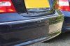
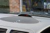
I’m delighted with the result, particularly as the Display Unit matches the light grey dash on my car and looks as if it could have been an original fitment. I think the sensors look good too and match the paintwork very well. The pics show the rear strip complete with sensors, and the display showing an obstruction to the right rear.
1. Fitting the sensors
I used these sensors - http://abarnard.ecs2.co.uk/4004-reversing-sensors-with-digital-display.asp - which I colour matched as per the website instructions with spray paint from Paints4u, 2 thin coats of colour, one of clear.
Firstly remove the rear bumper strip which is held on with clips. It is necessary to remove the outer strips (which go round the corner to the wheel arch) first. Note that the end nearest the wheel arch is held on with a screw inside the arch lining, if you don’t remove this the little bracket breaks (don’t ask how I know this…!) though as the clips seem strong this is not a problem and the strip holds fine. Check the gaps between centre piece and corners as you need to recreate the same gap later, when fitting or you end up with the centre bit too much to one side and have to do it again (don’t ask how I know this either….!). Preferably use something plastic to lever off the strip to avoid damage. Incidentally, any scratches can be touched in by spraying a little of the paint mentioned above into the aerosol cap and applying with a small brush.
The centre strip has four circles (very faint) marked in the plastic to show where the sensors should be fitted. I found the centre of the circles by making a circle the same size with a pair of compasses, cutting out then holding in the circle on the plastic and marking the centre with an awl. I used a small drill to drill through from the inside, then used the hole cutter supplied in the kit from the outside. I cleaned up the hole with a knife (the plastic tends to melt slightly and stick) then fitted the sensors.
The bumper itself already has the holes for the sensors, though the outer ones have a strip of plastic across the centre of the hole which needs to be cut off with a sharp knife.
Feed the sensor wires along inside the bumper right to left.
Now remove the internal trim from the boot. There are round and oblong plastic clips holding this on, all work on the same principle and the centre part should be removed, then the clip itself. The rear part around the lock should be removed first then the nearside trim which covers the lamp and rear SAM.
Below the rear lamp is a large rubber bung which, when removed, leaves a hole which lines up with the nearside sensor, the sensor wires should be fed through this hole. It is possible to obtain a grommet for this hole, but I simply cut a cross in the middle of the rubber bung and pushed the wire connectors through. A dab of silicone will seal this up later.
Refit the centre strip while pulling on the sensor cables to tighten them up and avoid them being trapped. It is a good idea to fit one of the corner bits first and ensuring the gap is correct when fitting the centre
2. Fitting the control box
I decided to use a relay on the reverse light to avoid CANBUS or bulb sensor problems, this may or not be necessary. The relay and the control box were stuck with double sided tape to the rear SAM (which was detached to make things easier). The relay was provided with a feed from a suitable ignition switched power source, reverse sensing from the wire leading to the reverse light, earth and connection to the control box. The control box was also earthed and all the sensors attached. All wiring was done using ‘piggyback’ connectors, not elegant but functional, and they can be removed at a later stage. At this stage the system was tested by connecting the display unit, putting the car in reverse and approaching the rear from all angles while watching the display.
3. Fitting the Display unit
This is the tricky bit. The wire from the Display unit has to pass from the front of the car through to the boot. After much experimentation, the following was found to be the easiest method.
a) The console trim was removed, as was the radio. (This is covered elsewhere so I won’t repeat here). The speaker cover on top of the dash was removed (This simply levers out, but use something plastic to avoid damaging the dash.
b) The cover under the glove box was removed (two screws just below the front of the glovebox) and allowed to hang down.
c) The left footwell trim was removed. This is held on with a central screw hidden by a small cover, and two clips under the weatherstrip. It is necessary to pull the weatherstrip off to access and lever off these clips.
d) The front and rear door carpet trims were removed, these pull off, though the rear one is also clipped at its front end so pull up to remove then pull back to slide off the front clip. Below these is a plastic conduit where the existing wires run through to the rear, etc.
e) The rear seat squab is pulled up on the nearside to allow access to the bolt which holds the bottom of the rear seat back. When this is pulled back the wiring through to the boot can be seen.
f) From inside the boot, just above the wheel arch on the nearside, a large piece of foam is removed to allow access between the boot and the interior of the car.
g) The Display Unit was positioned on the top of the speaker cover and a small cut made on the NSF to allow the wire to pass through. The Display Unit wire is then fed over the speaker bracket and down the front of the console into the place where the ashtray fits. It is then possible to feed the wire through into the passenger footwell.
h) At this stage the Display Unit can be glued to the speaker cover using the supplied double sided tape and the speaker cover, radio and console trim refitted.
i) The wire is taken along below the glove box and down the side panel into the conduit under the door carpet trims, through to the back of the car and up and over the wheel well into the boot and connected to the Control Unit.
And that’s it in a nutshell. Obviously take care to route the wires where they will not be damaged, or get in the way of anything else, Tape wires together and tape to existing cable runs for neatness, and put everything back the way it was. A wedge shaped piece of plastic is the best thing to use for levering the various bits off, I used one that came with a Brodit mobile phone/pda holder kit.
I’m delighted with the result, particularly as the Display Unit matches the light grey dash on my car and looks as if it could have been an original fitment. I think the sensors look good too and match the paintwork very well. The pics show the rear strip complete with sensors, and the display showing an obstruction to the right rear.