JoeHorner
Senior Member
- Joined
- Aug 21, 2022
- Messages
- 133
- Reaction score
- 166
- Your Mercedes
- 2003 W203 C270CDI Elegance
Thought this might be of use to someone out there.
After a year of not getting round to fully diagnosing it, a couple of weeks ago confirmed that the intermittent "limp" on our W203 C270CDI was being caused by an ECU fault (bad internal barometric pressure sensor). The sensor isn't available as far as I could find so the only solution was to replace the ECU. The obvious options were to buy a renewed ECU and fit using xentry or pay for someone to clone the existing one. Both would have been about £250 - £300 which would have been worth it but I hate paying when I don't need to.
The ECUs are available from a certain auction site from about £30-£40 but, obviously, won't just plug & play thanks to the drive authorisation system. A fair bit of digging around on less reputable forums showed that the relevant data is held in a 5P08 eeprom chip. This is a 1kB serial eeprom which is so old now that most current eeprom readers don't know how to deal with it. But it uses an SPI interface, which is available with the good old Arduino. A few evenings playing with the chip's data sheet and writing some code produced a system which would happily read the contents of the old ECU and then write them to the new one, verifying the write as it goes.
If you had to buy everything new, total cost of building the programmer would be under £25. I had everything lying around so cost was basically nothing!
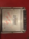
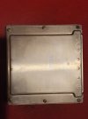
Here's the ECU (for recognition purposes):
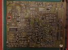
After opening (6x torx screws) the eeprom chip is conveniently visible on the underside of the board:

Having built the programmer using a breadboard (details and Arduino code below), all that was needed was to connect to the chip. You can do that by carefully soldering 6 fly-leads to its pins or using an SOIC8 test clip if you have one handy:
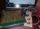
And then power up the arduino. You don't need to have it connected to a computer but having the output going to the arduino serial monitor gives useful feedback that everything's working properly. The initial screen once powered up looks like this:
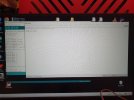
Pressing the "read" button on the programmer (the LH one in the layout below, connected to Arduino pin 7) will start the read process:
Note that, if the values coming up on the screen are ALL "FF" then it means there's a problem and it's failing to read properly. Check your connections and try again!
Once you're happy with the read, disconnect from the old ECU and connect to the new one. Then press the "Write" button and wait for it to complete. It writes in 4 blocks blocks of 256bytes each, and reads each byte back after writing to verify a successful write. The verification is reported at the end of each block:
Once you're done, disconnect, put the lid back on, fit to your car and you're done. The car simply won't know it's not using the old ECU anymore
It's worth noting that it'll likely be quite lumpy for the first minute or two as the "new" ecu gets used to the new engine's needs.
The Arduino circuit is as follows. I had to use a 25LC chip in the layout because I didn't have an icon for a 5P08 but the connections are exactly the same (with the writing the same way up). The SD module connections, from top to bottom, are:
* Gnd
* +5v
* MISO
* MOSI
* SCK
* CS
The arduino code (with far too many comments included) is in the attached file if anybody needs it.

After a year of not getting round to fully diagnosing it, a couple of weeks ago confirmed that the intermittent "limp" on our W203 C270CDI was being caused by an ECU fault (bad internal barometric pressure sensor). The sensor isn't available as far as I could find so the only solution was to replace the ECU. The obvious options were to buy a renewed ECU and fit using xentry or pay for someone to clone the existing one. Both would have been about £250 - £300 which would have been worth it but I hate paying when I don't need to.
The ECUs are available from a certain auction site from about £30-£40 but, obviously, won't just plug & play thanks to the drive authorisation system. A fair bit of digging around on less reputable forums showed that the relevant data is held in a 5P08 eeprom chip. This is a 1kB serial eeprom which is so old now that most current eeprom readers don't know how to deal with it. But it uses an SPI interface, which is available with the good old Arduino. A few evenings playing with the chip's data sheet and writing some code produced a system which would happily read the contents of the old ECU and then write them to the new one, verifying the write as it goes.
If you had to buy everything new, total cost of building the programmer would be under £25. I had everything lying around so cost was basically nothing!
Here's the ECU (for recognition purposes):


After opening (6x torx screws) the eeprom chip is conveniently visible on the underside of the board:


Having built the programmer using a breadboard (details and Arduino code below), all that was needed was to connect to the chip. You can do that by carefully soldering 6 fly-leads to its pins or using an SOIC8 test clip if you have one handy:

And then power up the arduino. You don't need to have it connected to a computer but having the output going to the arduino serial monitor gives useful feedback that everything's working properly. The initial screen once powered up looks like this:

Pressing the "read" button on the programmer (the LH one in the layout below, connected to Arduino pin 7) will start the read process:
Note that, if the values coming up on the screen are ALL "FF" then it means there's a problem and it's failing to read properly. Check your connections and try again!
Once you're happy with the read, disconnect from the old ECU and connect to the new one. Then press the "Write" button and wait for it to complete. It writes in 4 blocks blocks of 256bytes each, and reads each byte back after writing to verify a successful write. The verification is reported at the end of each block:
Once you're done, disconnect, put the lid back on, fit to your car and you're done. The car simply won't know it's not using the old ECU anymore
It's worth noting that it'll likely be quite lumpy for the first minute or two as the "new" ecu gets used to the new engine's needs.
The Arduino circuit is as follows. I had to use a 25LC chip in the layout because I didn't have an icon for a 5P08 but the connections are exactly the same (with the writing the same way up). The SD module connections, from top to bottom, are:
* Gnd
* +5v
* MISO
* MOSI
* SCK
* CS
The arduino code (with far too many comments included) is in the attached file if anybody needs it.


