flyboy737
New Member
- Joined
- Dec 17, 2009
- Messages
- 4
- Reaction score
- 4
- Location
- Centurion - South Africa
- Your Mercedes
- 2007 Merc C320CDI
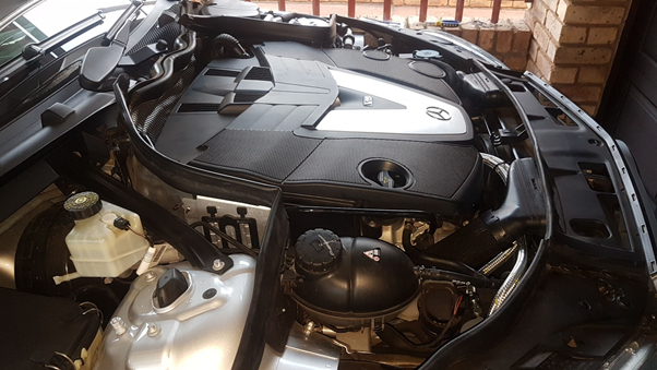
ou will find numerous posts here and on other forums about the OM642 engine venting oil into the turbo intake.
This was my motivation to do the job.
This pictorial will cover the process from start to the completed fitment.
So to keep you interested I'll show you the end result first.....
Because I'm an enthusiast, I did NOT want to cut or damage any of the original panels. I wanted (and achieved) the ability to take the car back to original, without ANY evidence of the modification, to preserve originality and resale value.
I include pictures of the complete manufacturing process of the oil catch can as well, BUT, I believe most people would prefer just buying an "off the shelf" catch can to use Google: D1 Spec for an example.
I live in South Africa and have some experience around the work shop. So I opted to use my local hydraulic guys (Hydra Part in Centurion), as they have a well equipped workshop and keen people. My technician was Adriaan.
We used a 2 inch steel pipe was capped on both ends and trimmed down to make it lighter.
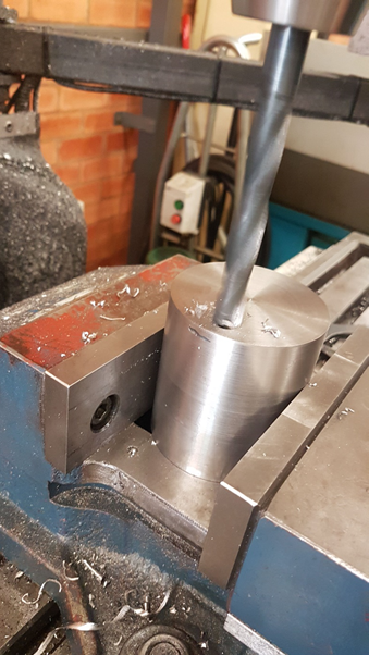
This hole is the feeder (input) from the Pressure Control Valve (PCV) Valve.
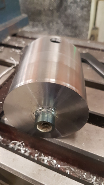
A sump plug for the bottom of the tank so the oil can be drained off (and properly recycled) and the side hole will be the return line to the turbo intake.
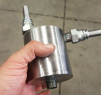
This is the catch can with the connectors done!
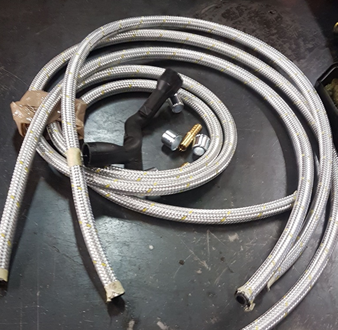
Now on to the plumbing. We used 11mm (inside diameter) braided heat resistant hydraulic pipes to be BOTH heat and oil resistant.
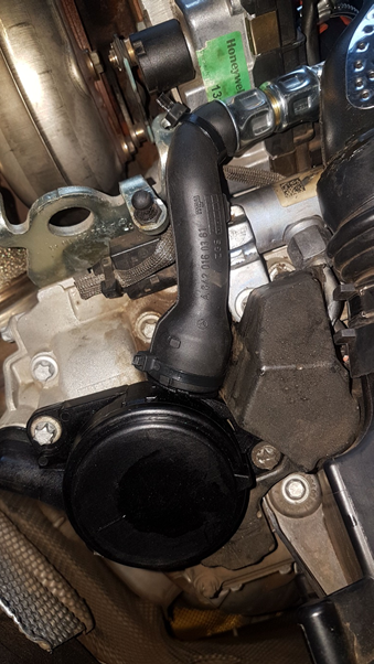
The black rubber pipe is the original PCV to turbo pipe.
I opted to replace the PCV valve and air sensor and the kit came with a new hose, so I was prepared to sacrifice the old hose to get a good result.
This pipe was cut in the middle and connected to the extension pipes, to vent the PCV valve to the Catch Can and the return to turbo line.
The brass insert and collars are to make for a perfect connections.
The collar connections are crimped in this machine.
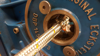
And the results are impressive...

So the next thing was to position the catch can. I didn't want to drill any holes, so I opted for a bracket behind the R/H headlight on my C320 CDI.
You can see the original 2 x 10 mm bolts and bracket we used in the second picture below..
and here - note the two bolts from the existing bracket.
The new PCV valve was fitted and here is the original pipe to braided hose connection making an excellent fit.
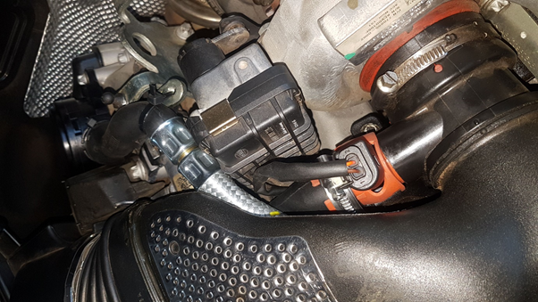
This picture is from the vehicle Left.
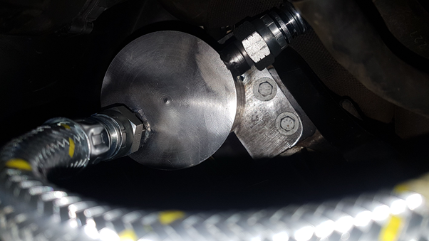
This picture shows the PCV valve to Catch Can line, using the first half (of the cut original line) joined into the braided line to the Catch Can.
The second half, is attached to the return line from the Catch Can to the Turbo and attached to the orange rubber covered air flow sensor in the centre of the picture.
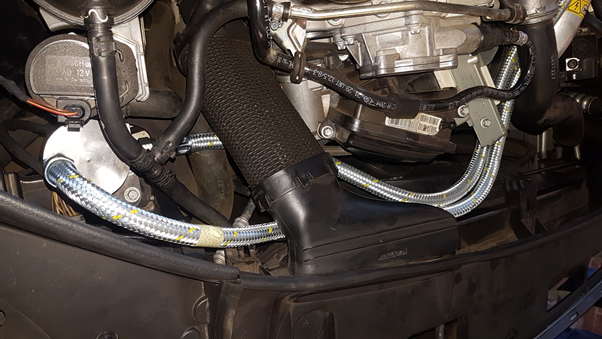
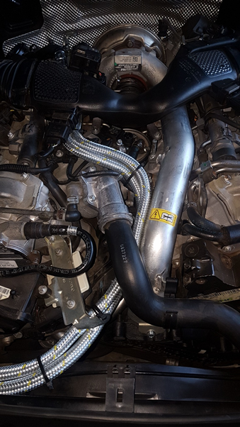
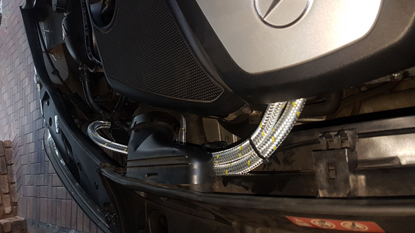
The routing of the lines took a bit of time to finalize. The engine cover has fins to ensure component cooling, and I wanted to leave everything original and NOT remove any of these fins. Here is the final routing of the lines:
The Oil Catch Can was sprayed with a grey primer and fitted to a base plate onto the existing bracket behind the R/H headlight.

and another view...
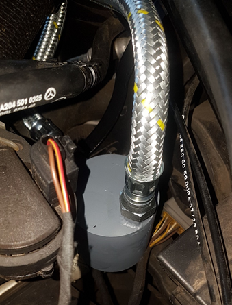
The Braided hoses were secured using several zip-ties
And I'm very happy with the final outcome.
I believe it looks professional and achieved what I set out to achieve.

I hope this helps some of you who might be thinking of doing the same.
It should be easier on the E / S / ML / GL / and R models using the OM642 engine, as you should have more space to fit the Catch Can than I had on the C - Class!
This was my motivation to do the job.
This pictorial will cover the process from start to the completed fitment.
So to keep you interested I'll show you the end result first.....
Because I'm an enthusiast, I did NOT want to cut or damage any of the original panels. I wanted (and achieved) the ability to take the car back to original, without ANY evidence of the modification, to preserve originality and resale value.
I include pictures of the complete manufacturing process of the oil catch can as well, BUT, I believe most people would prefer just buying an "off the shelf" catch can to use Google: D1 Spec for an example.
I live in South Africa and have some experience around the work shop. So I opted to use my local hydraulic guys (Hydra Part in Centurion), as they have a well equipped workshop and keen people. My technician was Adriaan.
We used a 2 inch steel pipe was capped on both ends and trimmed down to make it lighter.
This hole is the feeder (input) from the Pressure Control Valve (PCV) Valve.
A sump plug for the bottom of the tank so the oil can be drained off (and properly recycled) and the side hole will be the return line to the turbo intake.
This is the catch can with the connectors done!
Now on to the plumbing. We used 11mm (inside diameter) braided heat resistant hydraulic pipes to be BOTH heat and oil resistant.
The black rubber pipe is the original PCV to turbo pipe.
I opted to replace the PCV valve and air sensor and the kit came with a new hose, so I was prepared to sacrifice the old hose to get a good result.
This pipe was cut in the middle and connected to the extension pipes, to vent the PCV valve to the Catch Can and the return to turbo line.
The brass insert and collars are to make for a perfect connections.
The collar connections are crimped in this machine.
And the results are impressive...
So the next thing was to position the catch can. I didn't want to drill any holes, so I opted for a bracket behind the R/H headlight on my C320 CDI.
You can see the original 2 x 10 mm bolts and bracket we used in the second picture below..
and here - note the two bolts from the existing bracket.
The new PCV valve was fitted and here is the original pipe to braided hose connection making an excellent fit.
This picture is from the vehicle Left.
This picture shows the PCV valve to Catch Can line, using the first half (of the cut original line) joined into the braided line to the Catch Can.
The second half, is attached to the return line from the Catch Can to the Turbo and attached to the orange rubber covered air flow sensor in the centre of the picture.
The routing of the lines took a bit of time to finalize. The engine cover has fins to ensure component cooling, and I wanted to leave everything original and NOT remove any of these fins. Here is the final routing of the lines:
The Oil Catch Can was sprayed with a grey primer and fitted to a base plate onto the existing bracket behind the R/H headlight.
and another view...
The Braided hoses were secured using several zip-ties
And I'm very happy with the final outcome.
I believe it looks professional and achieved what I set out to achieve.
I hope this helps some of you who might be thinking of doing the same.
It should be easier on the E / S / ML / GL / and R models using the OM642 engine, as you should have more space to fit the Catch Can than I had on the C - Class!
")