Martin398
New Member
- Joined
- Jun 13, 2022
- Messages
- 8
- Reaction score
- 2
- Your Mercedes
- 2003 C Class C200 CDi 722.6 transmission
I have a 2003 C200 CDi with 722.6 gearbox.
Code readers, including Snapon Solus give P2100 1-2,4-5 Shift Solenoid fault and the box is in limp mode (it drives in second gear and reverse only).
I have tested the electrical resistance of the 1-2,4-5 solenoid, the 2-3 solenoid, and the 3-4 solenoid from the connector at the transmission control module (TCM) and all 3 solenoids read 4.6 Ohms.
I have tried clearing the code with the Solus, but it returns. (I had hoped the Solus would allow functional control of the solenoids, but it doesn’t)
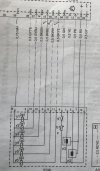
Below is the wiring diagram. I carried out some electrical checks but the answers I got have confused me and I am hoping someone can explain it to me.
Looking at the wiring diagram, I was expecting a ground-side-switched system, with Pin 38 (+) showing 12V, and, when the shift solenoids are operated, Pins 14, 15 and 16, would, in turn, be grounded as required. Instead, however, Pins 14, 15 and 16 are grounded all the time (key on, engine off or running, shift lever in park or moved through its positions), and there is practically no voltage on the white wire from Pin 38. With Pins 14, 15 and 16 being grounded all the time, clearly Pin 38 cannot be at 12V, otherwise all solenoids would operate together, so my thinking seems to be wrong. (These voltages were obtained with the TCM connected, by probing the wires.)
I have a spare TCM, and that shows the same behaviour.
(There is power on the red-white wire to Pin 20 from the front SAM. And the ground at Pin 30 brown wire is good.)
I’d be most grateful for help understanding when and how these solenoids are powered and grounded so that I might proceed with the diagnostics. There’s no point in my going any further if I don’t understand the operation. What am I missing?

Last edited:

